Published on · Simone Renzi
Revisions U9–U12; U13 development as of 4 November 2026
Work statusLocal tests documented; global robot kinematics and load capacity remain unqualified.
01 / Kinematics
A pose does not describe a robot’s range
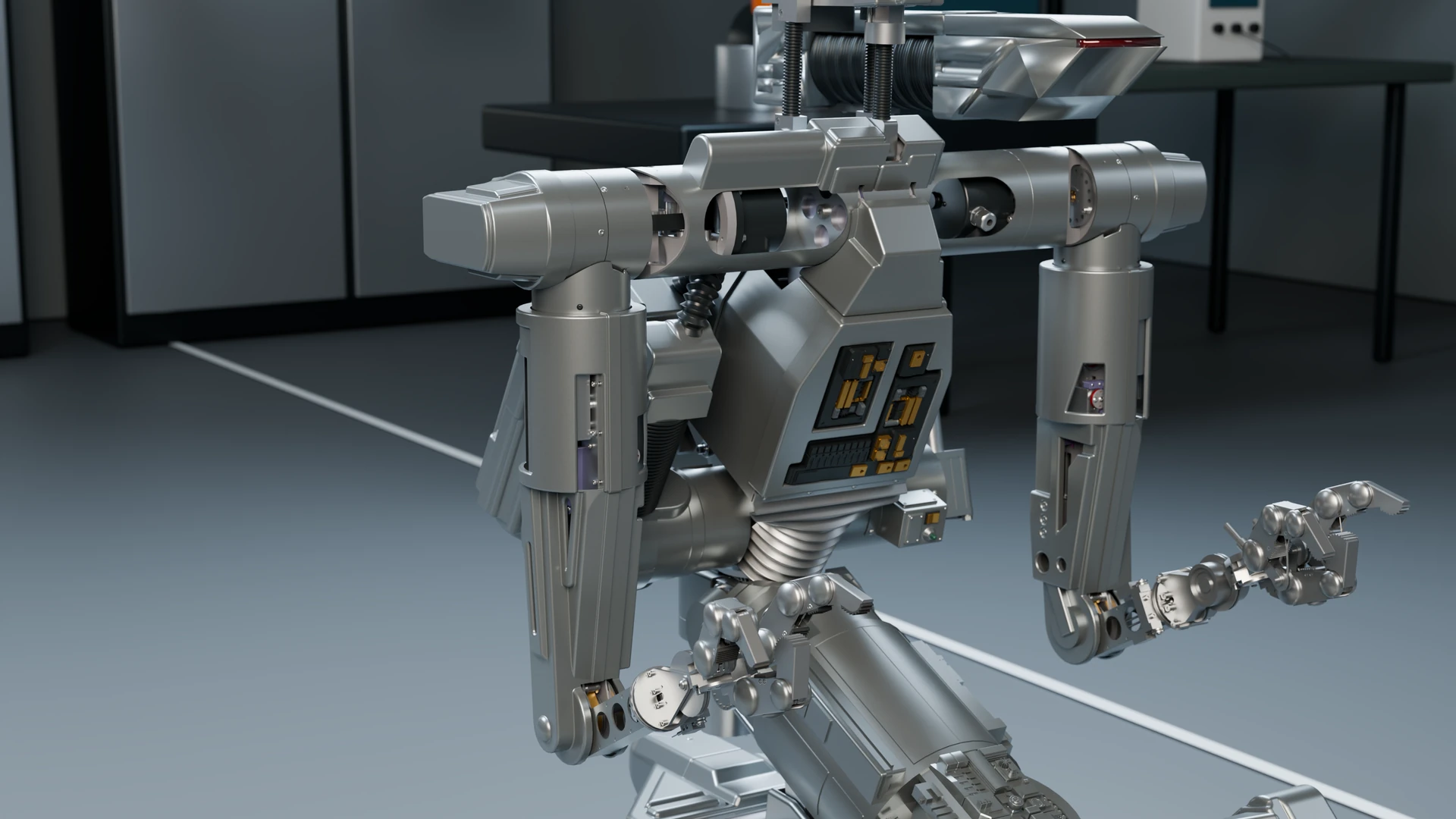
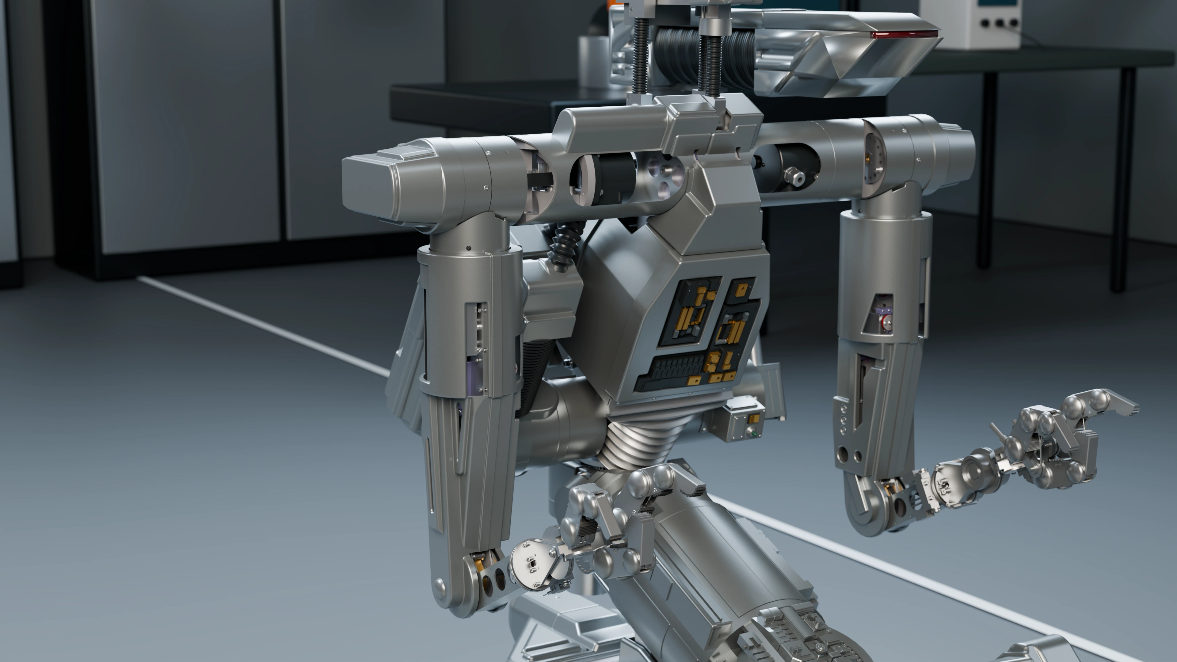
An assembly image shows one configuration. To understand whether Numero 5 can perform a movement, I must check which components follow the joint, whether references remain consistent and what happens when multiple axes change position together.
In my checks, I alternate native Fusion tests with geometric comparisons. Returning to neutral and reopening the archive are part of the check: a solution must remain reproducible after saving.
02 / Kinematics
The left elbow and the parts that follow it
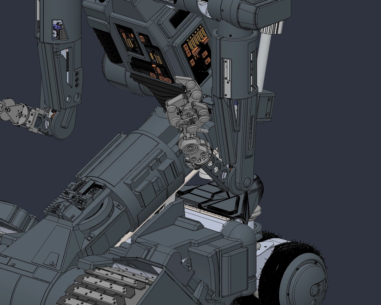
In U9, I replaced the left elbow’s rigid connection with a revolute joint on the actual hole axis. The pulley and spacers were associated with the forearm. The moving group contained 448 bodies within a 9,423-body assembly.
The initial seven sampled positions did not validate every trajectory. Later tests showed that an available single-joint range can become incompatible when the wrist rotates at the same time.
03 / Kinematics
Limits change after combined testing
In U10 R2, I retained a provisional CAD interval of ±15° at the elbow, ±90° for wrist rotation and ±30° for wrist flexion. Within this scope, 75 configurations and 12,885 comparisons were recorded without new unclassified collisions or calculation errors.
Fingers and other axes remained in their reference pose. That limitation is part of the result: samples alone do not guarantee continuous motion, and a software limit in CAD is not a physical stop on the robot.
04 / Kinematics
Later checks retain a defined scope
Following the U11 finger-segment correction, I added a continuous check in U12 R3 of the repaired cover against the left arm across three axes. This advances beyond a set of poses, but covers that housing and group while other movements remain fixed.
05 / Kinematics
The open work on the right arm
In the U13 report dated 4 November, the right elbow is still under development: its first test encountered old rigid groups that prevented motion. I am reconstructing the constraints in a separate copy, while U12 R3 remains the documented reference. I do not attribute an already qualified range to U13.
The requirement of 5 kg per hand remains to be verified together with actuators, brakes, transmissions and structure. In this journal, I also include results that require me to revise the work: recording a discovered limit is part of the project, not a stage to hide.
Documentation and references
For this account, I draw on project records, Fusion revisions and the checks described in the text. CAD views document their respective stages of development.