Published on · Simone Renzi
Separate U8 R2 variant
Work statusEnvelope study checked in a static pose; no qualified thermal or environmental-protection test.
01 / Thermal study
Protecting the computer while preserving airflow
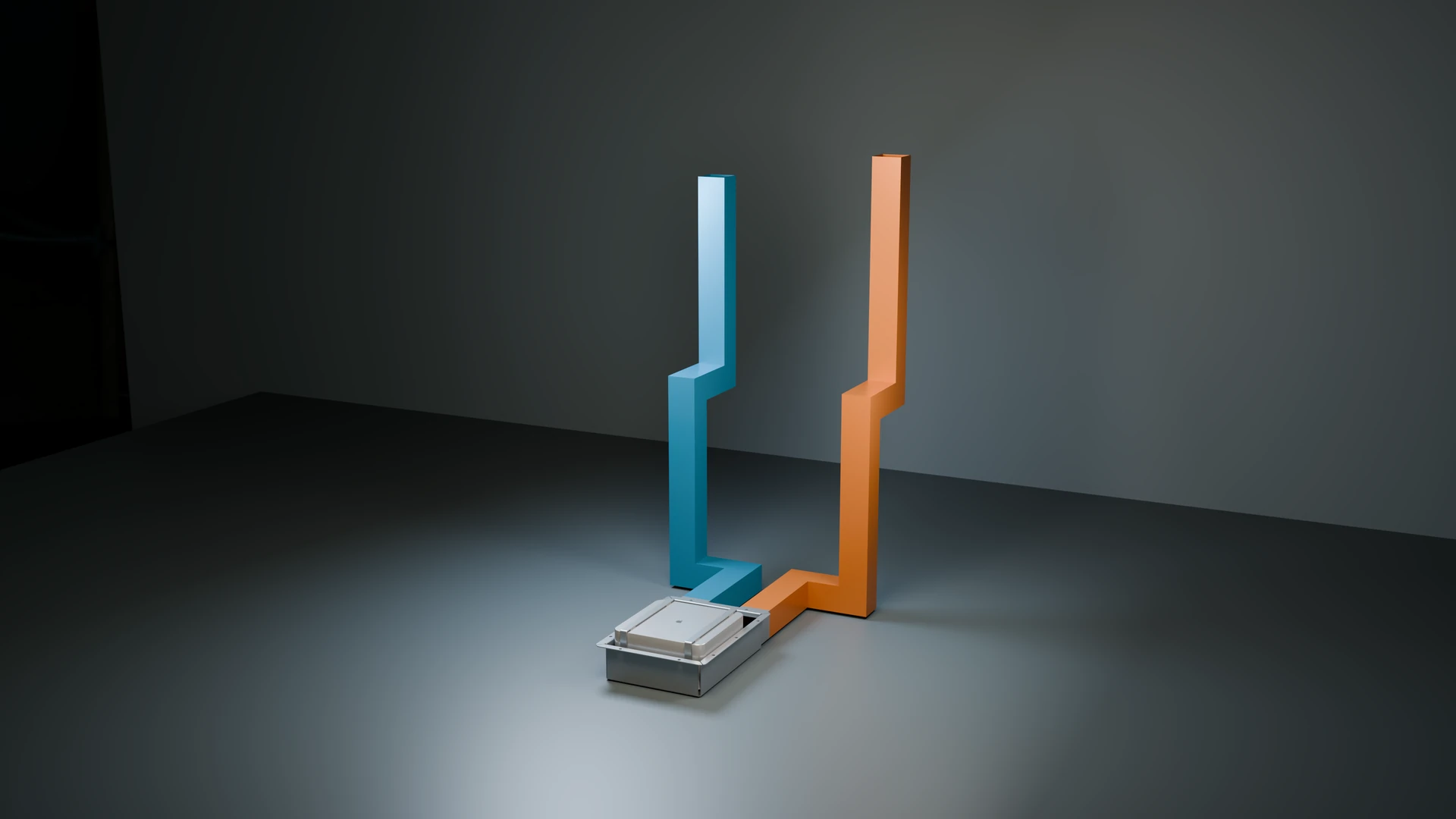
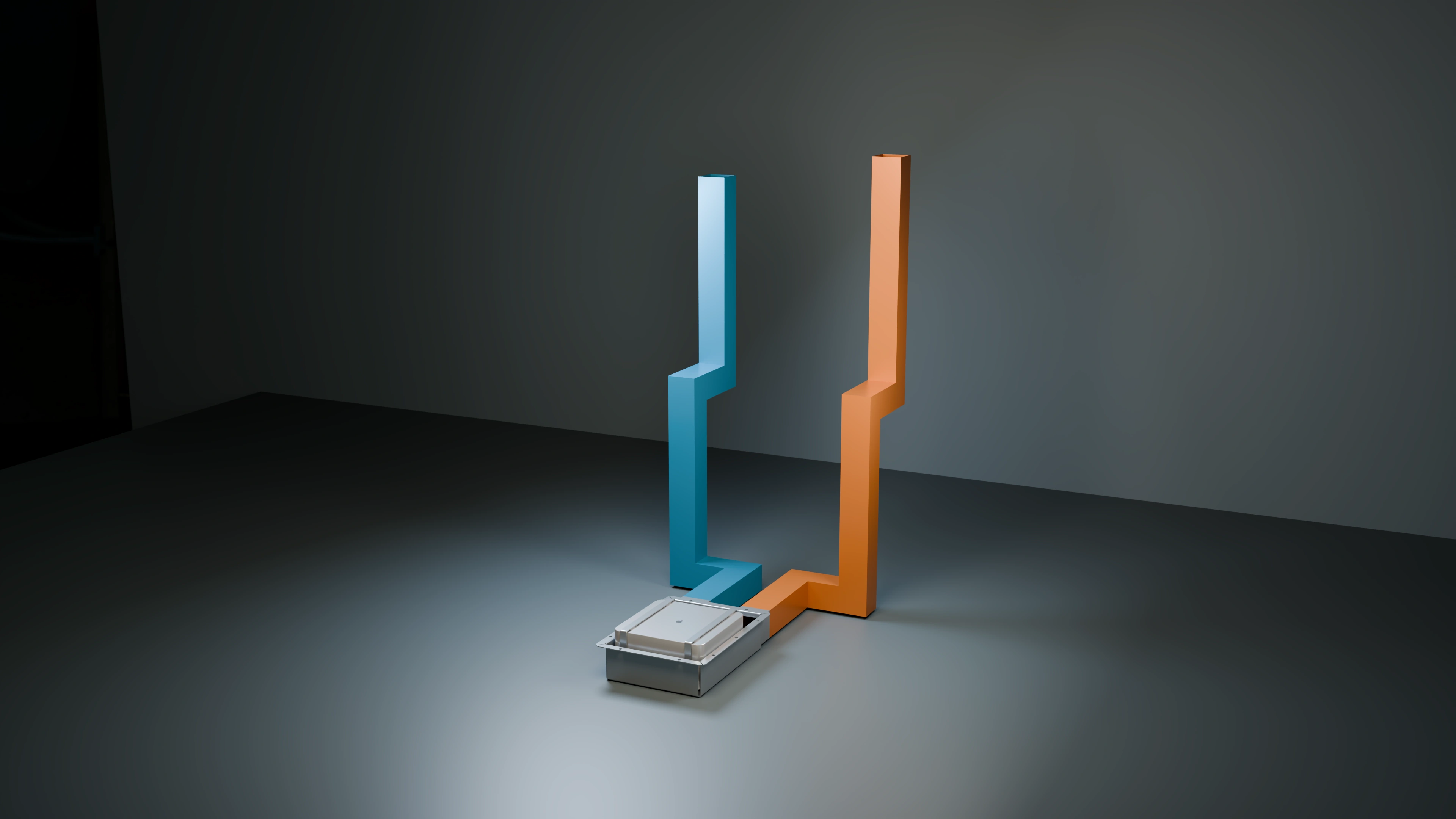
The Mac sits in the robot’s lower compartment, close to the ground. I therefore studied a protective tray with a lid and dedicated passages, retaining a specific requirement: no new ventilation holes in the outer shell. Enclosure protection must coexist with the computer’s air vents.
In the U8 R2 variant, I provided two separate paths, one for intake and one for exhaust. Blue and orange in the CAD views identify those paths; they are not the output of a fluid-dynamics simulation.
02 / Thermal study
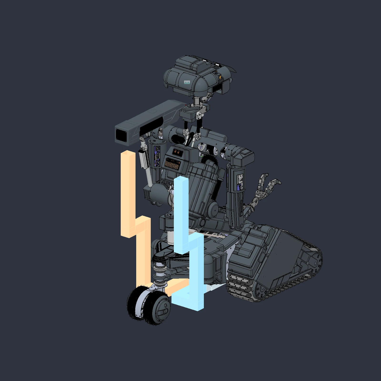
Why the ducts rise at the rear
Motors and plates occupy the direct central passage. The solution I studied passes under the base and rises externally at the rear through rear-facing connections. In the reference pose, the provisional terminals reach approximately 0.98 and 1.04 metres above the ground.
The rising ducts remain visible and are an envelope proposal. Final shape, bends, joints, supports, filters and terminals still require development. Raising an intake does not by itself demonstrate protection from dust or water.
03 / Thermal study
What was checked in Fusion
I saved and reopened the separate 30-body module. The static check included 119 solid comparisons and two conservative mesh-envelope checks, with no positive overlaps detected. Obstacle selection considered the index of 9,423 instances in the reference revision.
This check does not cover torso and rear-frame motion over their full travel. The variant remains separate from the main assembly: final integration also depends on those tests and service accessibility.
04 / Thermal study
The first thermal balance
In the preliminary calculation, I used 370 W as a conservative heat-removal assumption, based on the Mac Studio M2 Ultra’s stated electrical limit, not a measured AI workload. With air density of 1.16 kg/m³, specific heat of 1,005 J/(kg·K) and a 10 °C rise, the ideal balance gives approximately 114 m³/h.
I consider this a starting point. Pressure losses, recirculation and interaction with the Mac’s fans change the operating point. Flow passes through both intake and exhaust: it is not halved merely because there are two ducts.
05 / Thermal study
From study to enclosure testing
Next, I will need to separate flows near the actual vents, select fans and filters, and measure temperatures with the completed enclosure. I claim neither an IP rating nor a passed thermal test. My objective is to make cooling verifiable in the robot’s actual configuration.
Documentation and references
For this account, I draw on project records, Fusion revisions and the checks described in the text. CAD views document their respective stages of development.