Published on · Simone Renzi
Mount development through revision U6
Work statusCompartment and internal mount integrated in CAD; physical testing, power integration and cooling remain open.
01 / Mechanical integration
The computer choice changes the robot
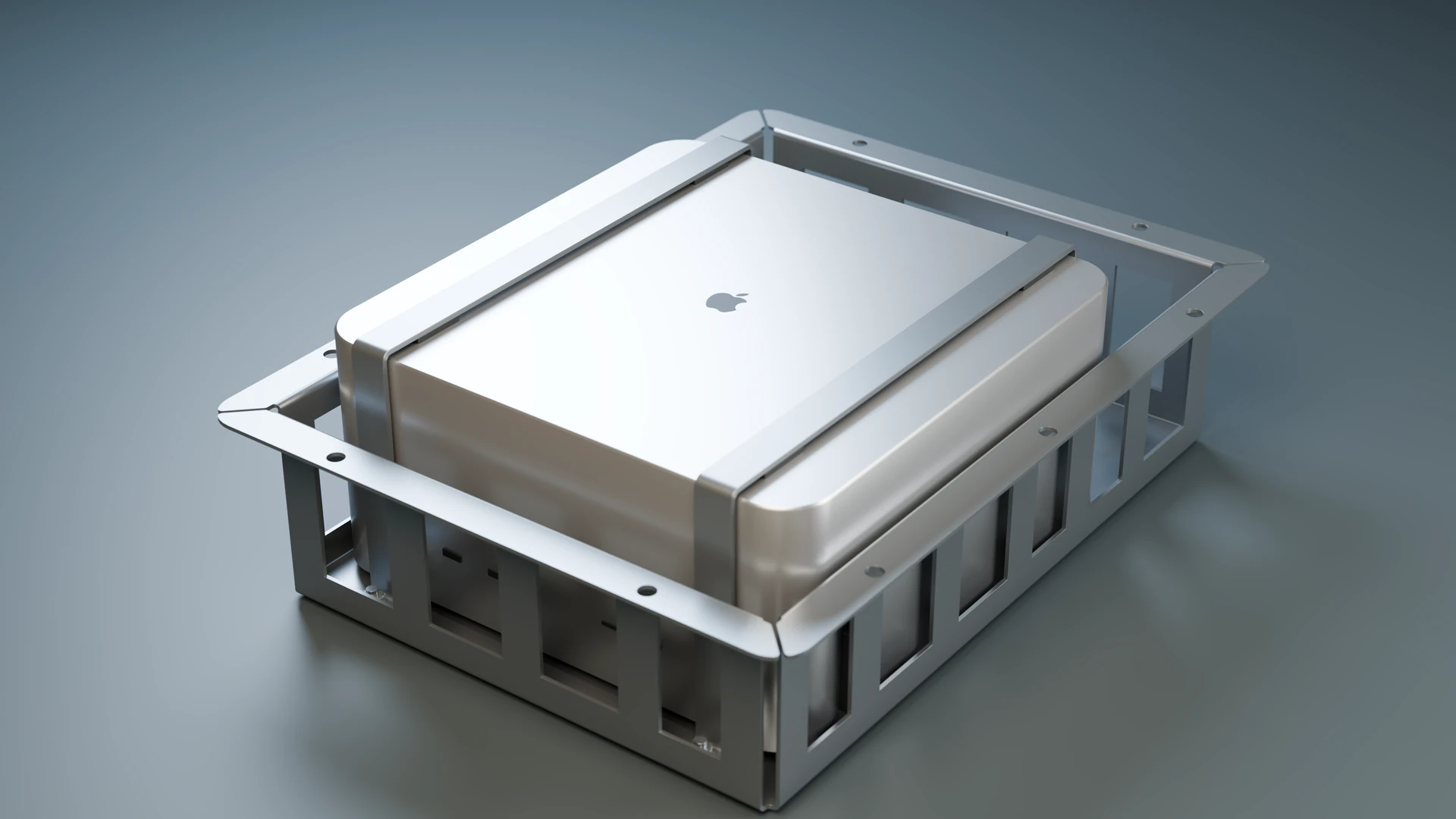
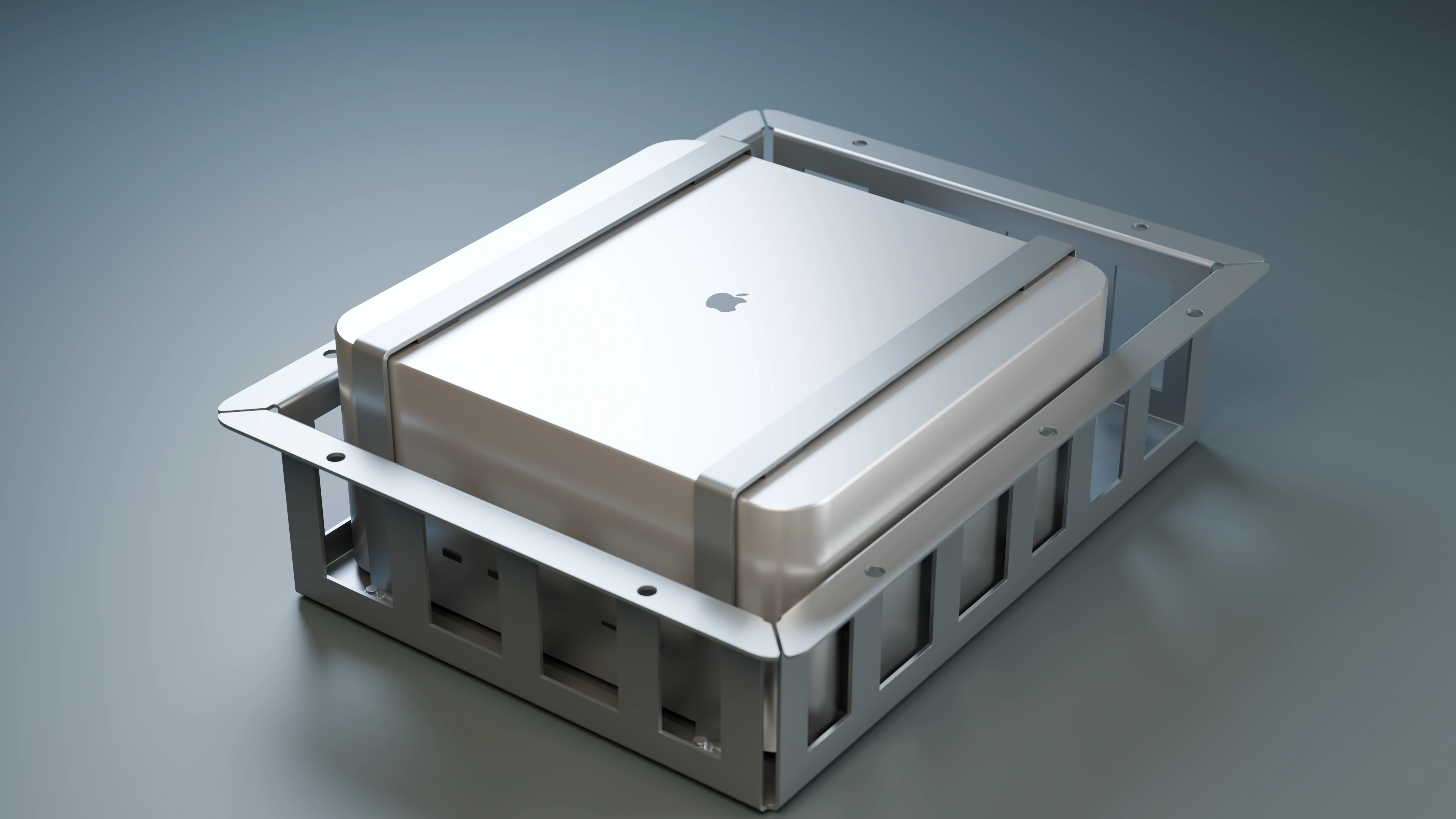
Carrying a 64 GB Mac Studio M2 Ultra onboard Numero 5 means reserving space for a complete computer. I had to consider its volume, mass, retention and servicing alongside the other base assemblies. The commercial envelope used in CAD is a reference, not a new component to manufacture.
The integration serves the local AI architecture: the Mac stays on the robot and provides services to the central controller. This decision has concrete mechanical consequences before the software is even started.
02 / Mechanical integration
From an external mount to the lower compartment
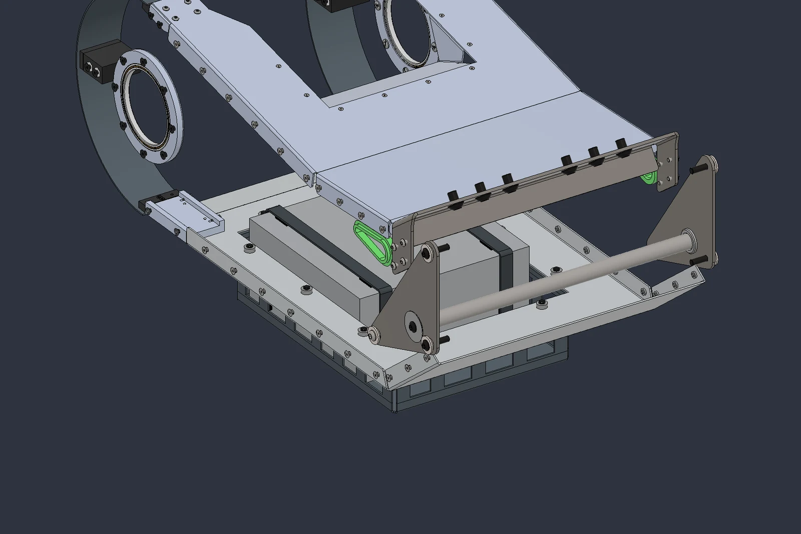
In the initial V7 solution, I used an external mount with a commercial MacCuff. In U6, I changed the approach: I placed the Mac in the lower central compartment between the track mounting points. The earlier mount and its 88 bodies were removed, and the affected plates restored.
The new group contains 26 bodies and retains approximately 74 mm of ground clearance in the documented neutral pose. The low position keeps the computer within the base, but requires specific consideration of protection, access and airflow.
03 / Mechanical integration
What supports the Mac
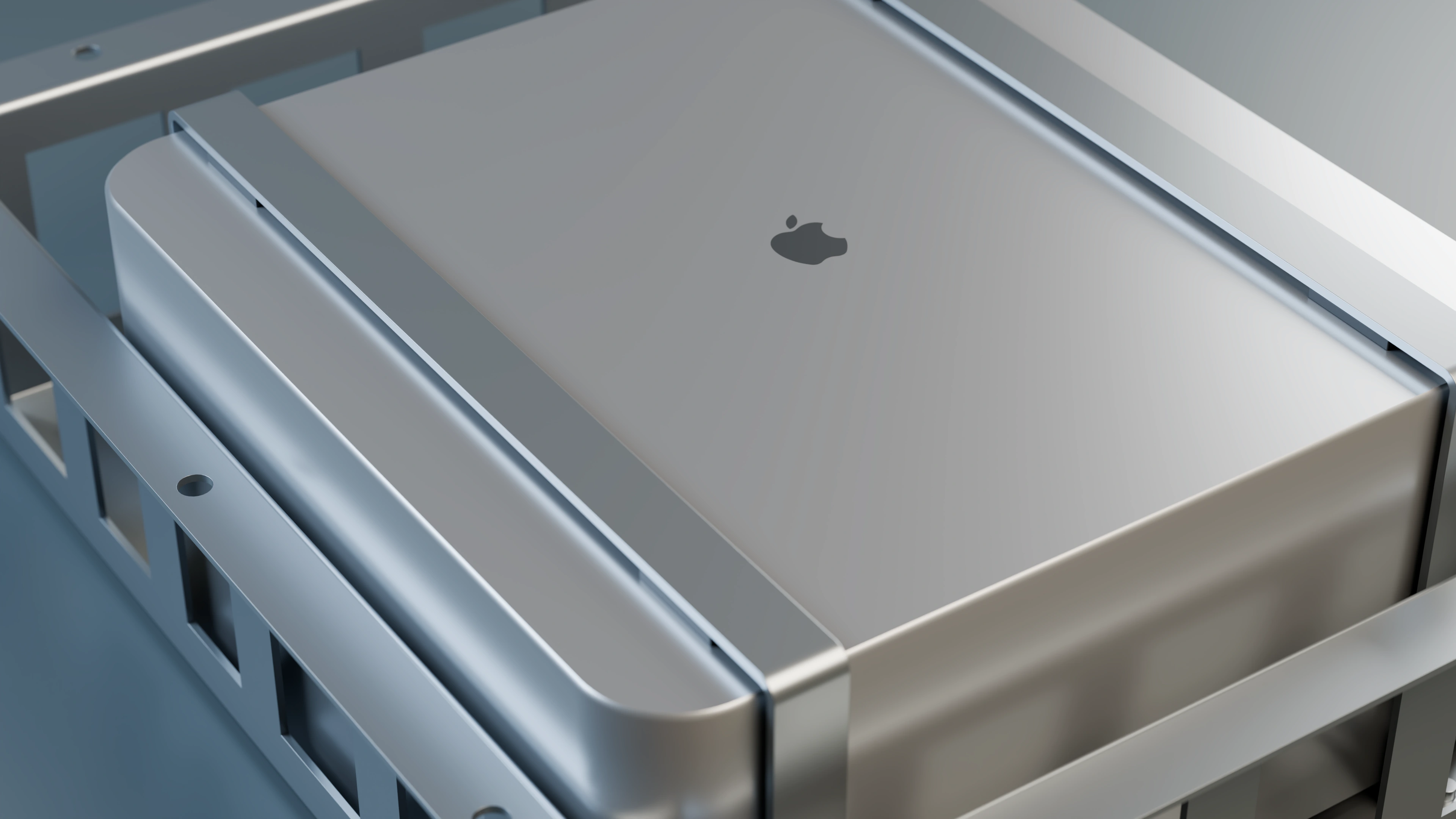
I organised the module around the tray, retainers, pads and represented fasteners. The documented estimate is approximately 4.29 kg for this group: 3.60 kg assigned to the Mac and approximately 0.69 kg to the new elements. Batteries, power conversion, cables and additional cooling remain excluded.
This value allows me to compare mount variants; it is not the robot’s final weight. Commercial components must also be compared with actual hardware, particularly where ports, feet and connectors affect the required space.
04 / Mechanical integration
Checks in the model
I saved and reopened U6, checking that it retained 9,378 bodies in total. Its record reports 108 native contact checks in the neutral pose and 41 sampled torso configurations; the four examined components remain at least 16.05 mm from the Mac in those poses. The result applies to that defined check scope.
05 / Mechanical integration
The compartment leads into airflow development
After positioning, I am continuing work on the protective enclosure and ducts. The U8 R2 variant is separate from the main assembly and should not be confused with an installed, operating system. Retention under load, servicing, power supply and thermal checks of the housed computer are checks I still need to complete before construction.
Documentation and references
For this account, I draw on project records, Fusion revisions and the checks described in the text. CAD views document their respective stages of development.