Published on · Simone Renzi
U12 R2 CAD integration · 3 November 2026
Work statusKit selected for purchase; CAD mounting integrated and reopened. Wiring, thermal and physical tests remain ahead.
01 / Electronics and mechanics
The selected model and exterior constraint
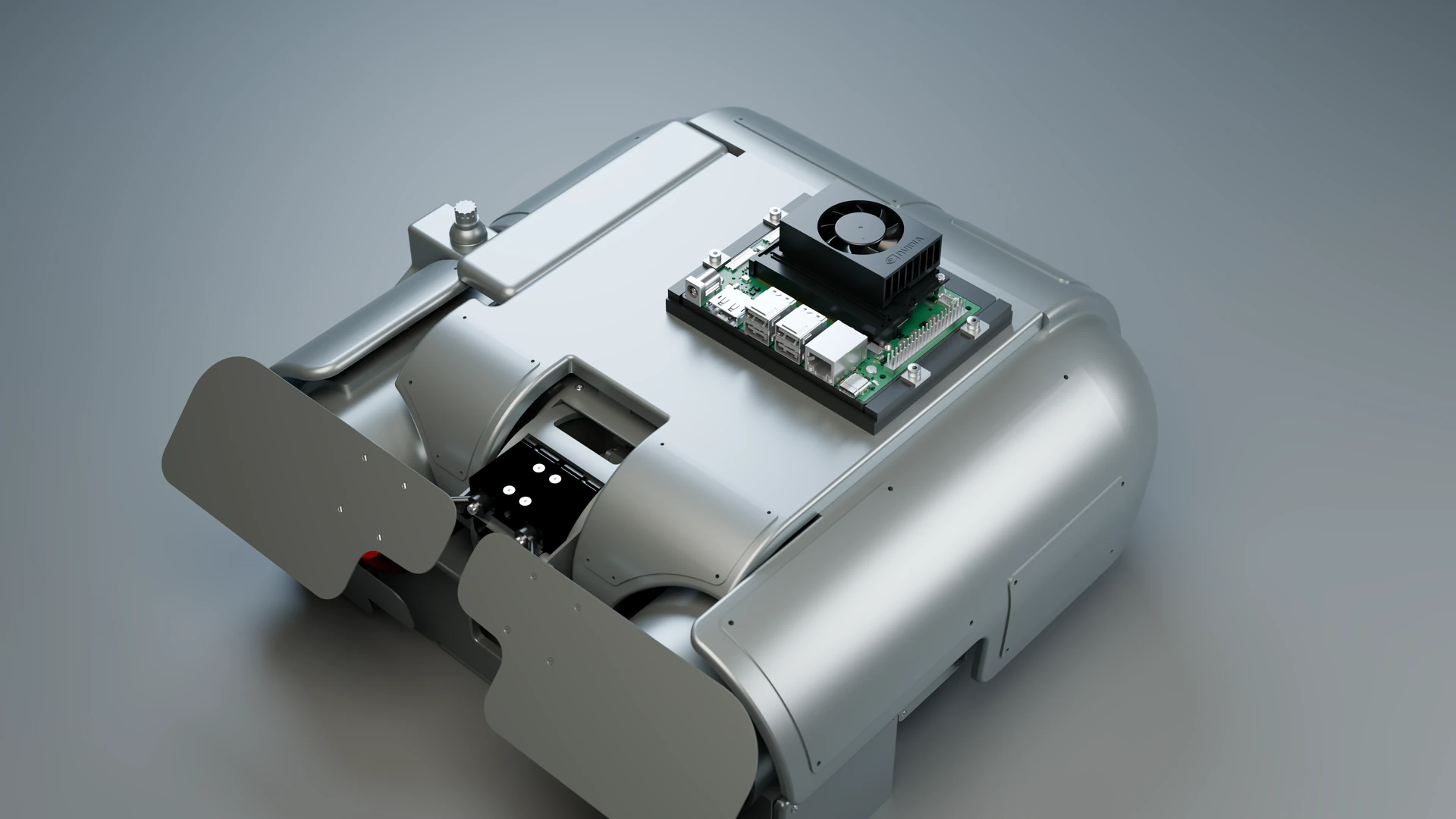
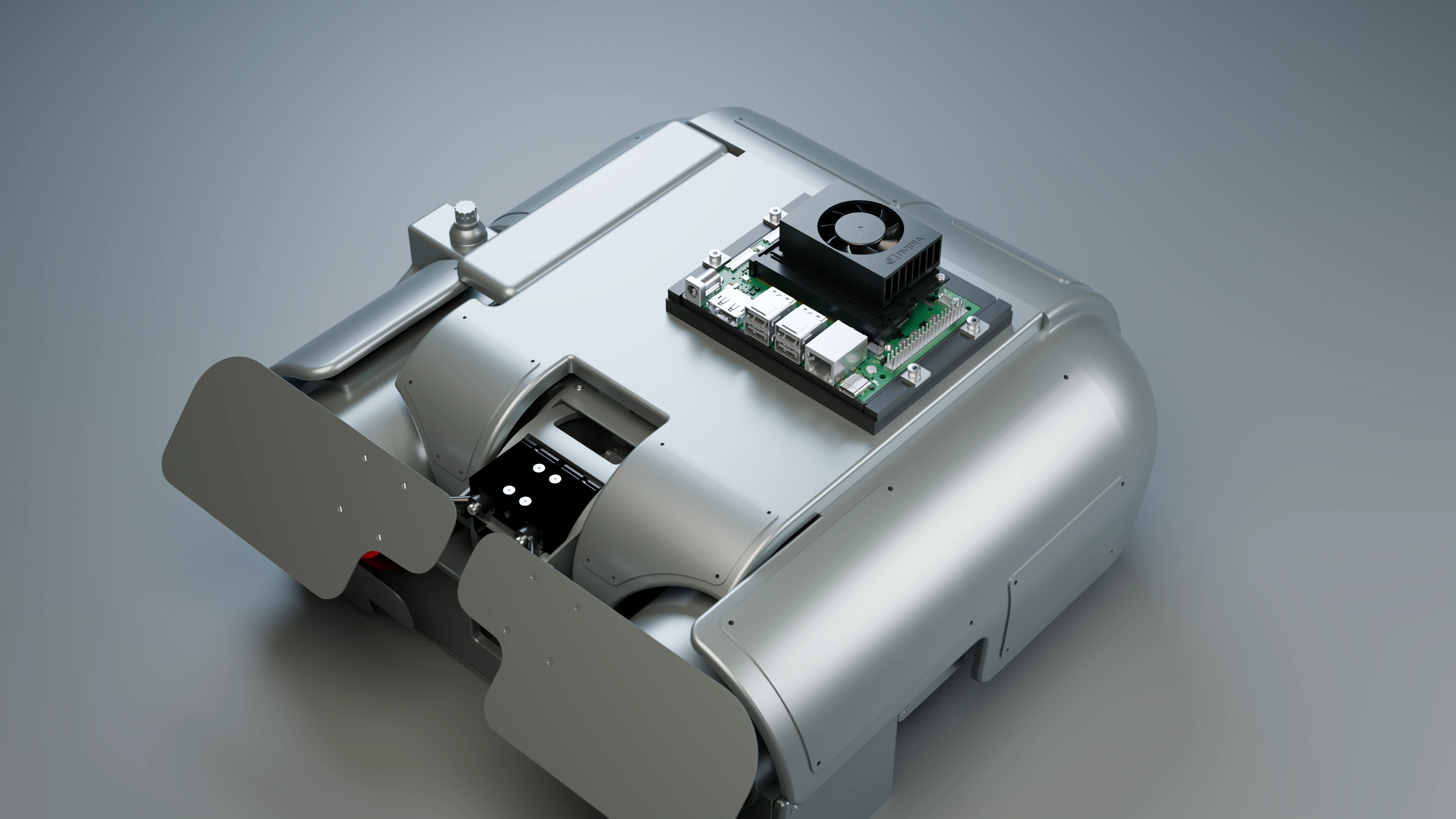
I selected the NVIDIA Jetson Orin Nano Super Developer Kit with 8 GB, part number 945-13766-0005-000. I still need to purchase it. It is intended as Numero 5’s central controller, with the Mac Studio in the base serving as the local AI server.
The mechanical constraint I set is to preserve the head exterior. Work therefore concerns the internal volume, mounting floor and kit support, without adding a visible enclosure or changing the shell profile.
02 / Electronics and mechanics
From the first mount to the R2 cradle
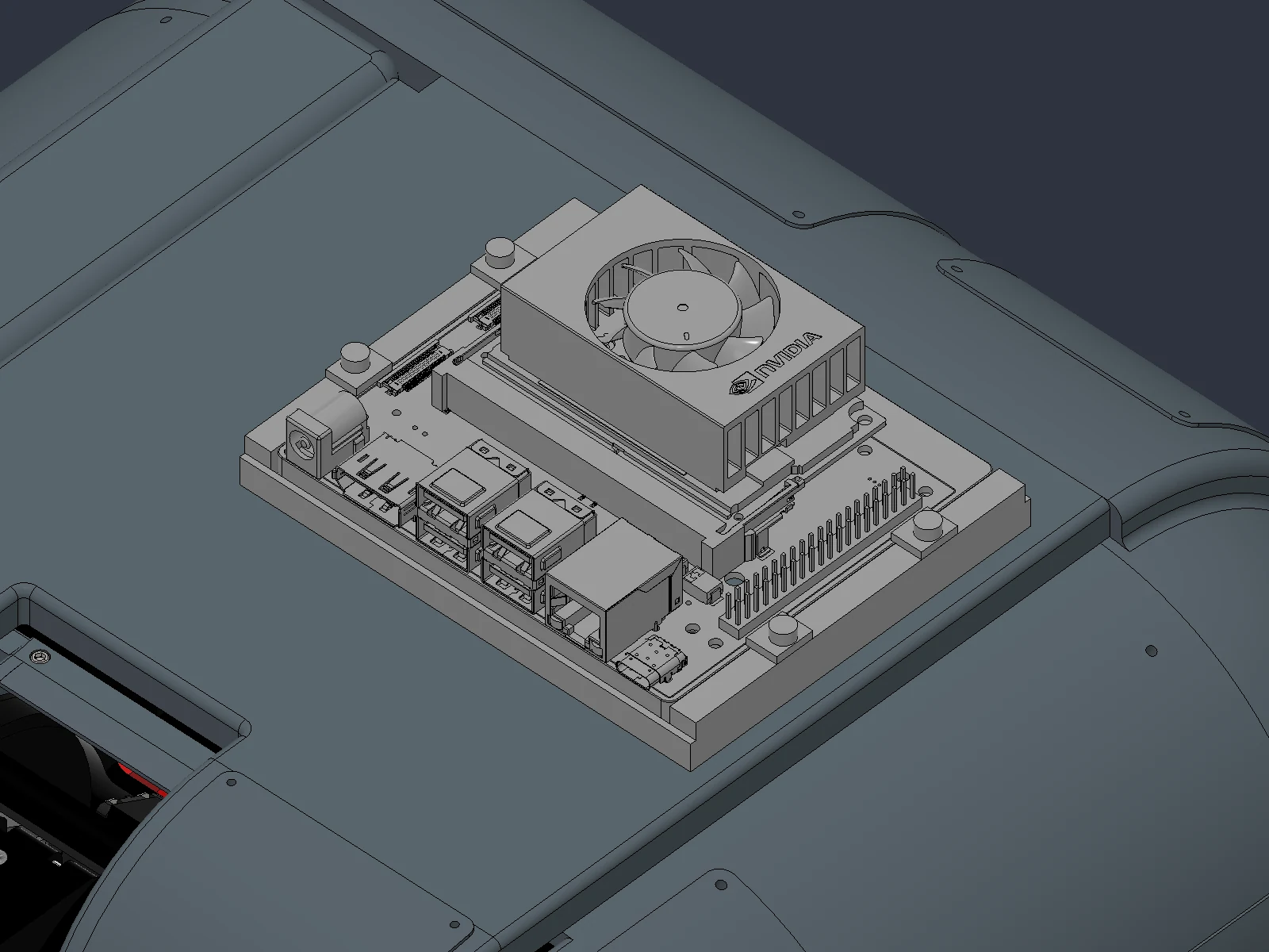
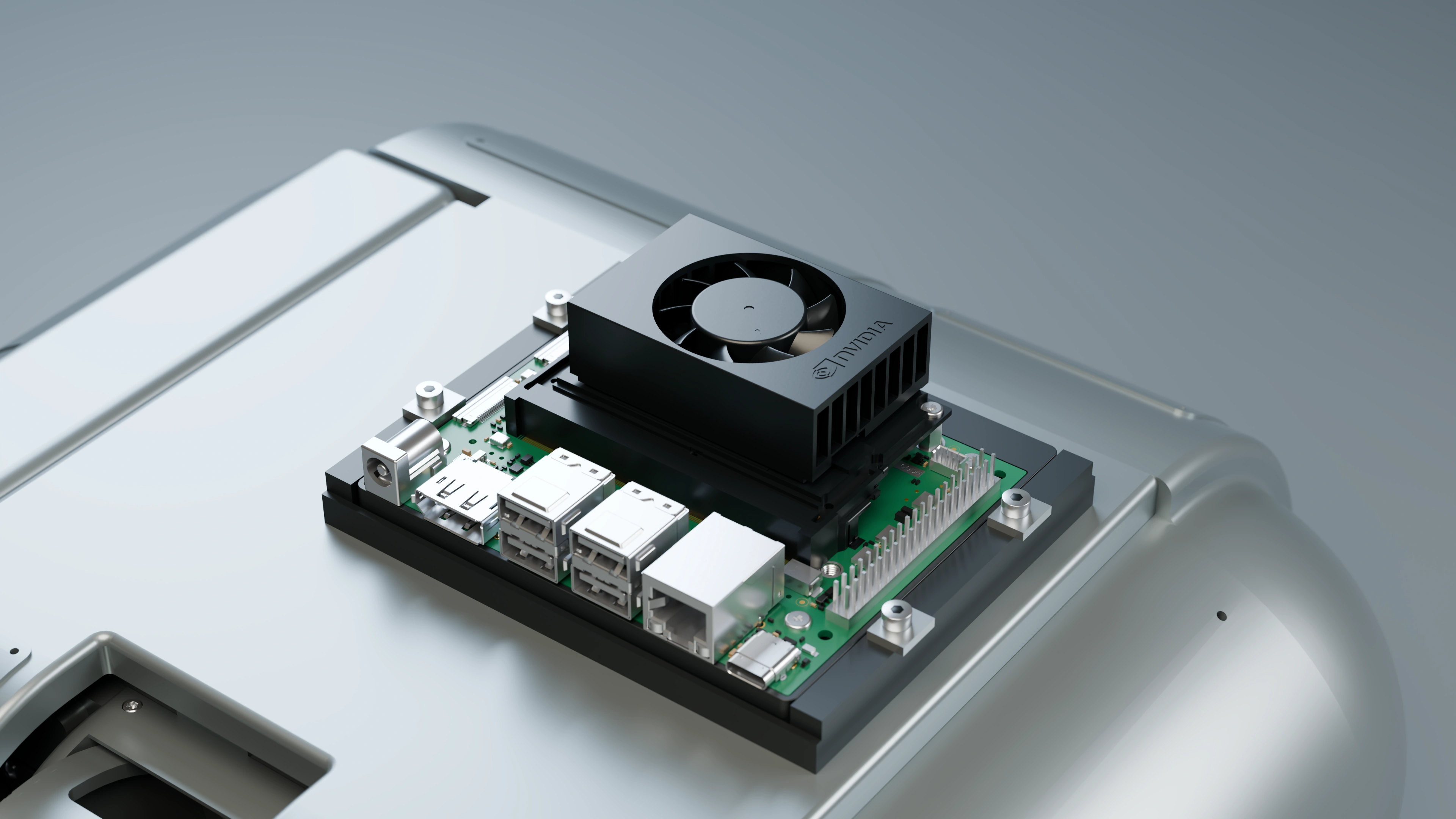
During detailed checking of the first mounting arrangement using M2.5 standoffs, I found three antenna interferences. In the R2 solution, I retained the complete kit, including its plastic base, heatsink, fan and antennas. An internal cradle supports the base, with four small plates retaining its edges.
I updated the internal floor for the new cradle’s four M3 fasteners and closed the previous holes in the model. The commercial kit remains intact. The cradle material and process still require qualification: the model documents a geometric solution, not an already manufactured part.
03 / Electronics and mechanics
Checking the moving parts too
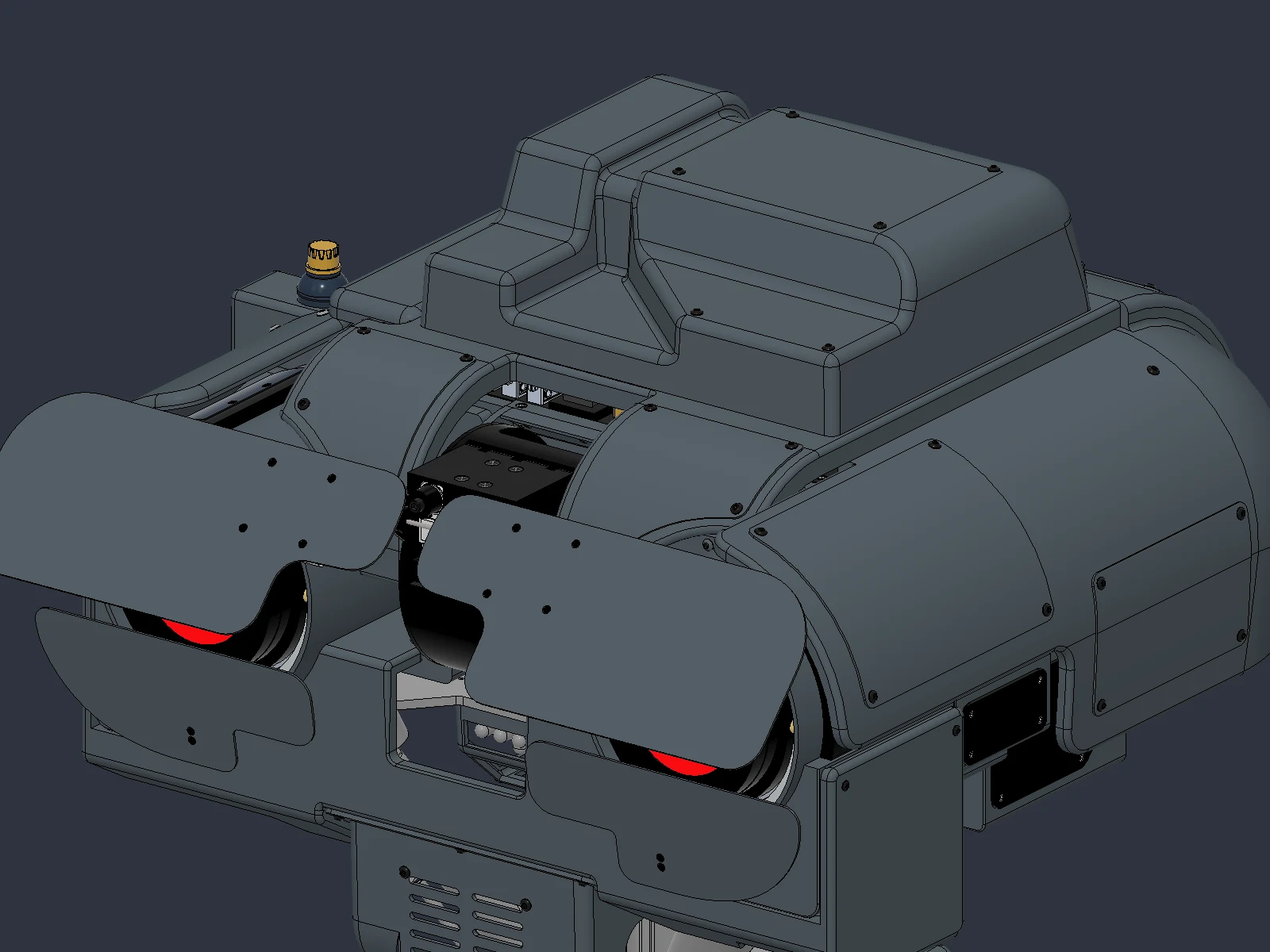
I integrated U12 R2 into the complete robot, then saved and reopened it with 9,476 bodies. Checks of the new group include comparing NVIDIA geometry positions with 34 source envelopes and 70 checks against actual head components.
Using twelve local poses, I checked that the group’s 56 elements follow the head and return to their initial position. Eyelid-to-kit separation was examined using conservative envelopes: this test does not give the eyelids a physical 360° range or qualify the entire robot.
04 / Electronics and mechanics
What changes with the Super version
NVIDIA states that the Super kit retains the original Developer Kit’s hardware and physical package. I therefore did not need to change the R2 cradle shape again when refining my choice of model. The module mode up to 25 W does, however, draw attention to thermal sizing, which must also include the carrier and peripherals.
05 / Electronics and mechanics
Testing with the head closed comes next
I still need to check plugged-in connectors, cable bend radii, strain relief, tool access and temperatures with the shell closed. CAD integration shows that an internal arrangement has been constructed and checked in the model; electronic and mechanical prototype testing must establish its real-world use.
Documentation and references
For this account, I draw on project records, Fusion revisions and the checks described in the text. CAD views document their respective stages of development.